Parker Hannifin Plc
Product Training
Hydraulic Fluids
And Contamination
Level 1
Hydraulic Fluids
Mineral Oils
Environmentally
Friendly Oils
Fire
Resistant Oils
Hydraulic Fluids
Mineral Oils
Environmentally
Friendly Oils
Fire
Resistant Oils

Level 1
Hydraulic Training
Hydraulic Fluids and Contamination
List of Figures
Figure
Page
1.1
The three main hydraulic oil groups…………………………………….. 4
3.1
Viscosity index graph……………………………………………………… 7
6.1
Photomicrograph of particle contamination……………………………. 13
6.2
ISO 4406 21/19/17 fluid photomicrograph………………………………13
6.3
ISO 4406 16/14/11 fluid photomicrograph………………………………13
Ref H F&C L1 0504
2

Level 1
Hydraulic Training
Hydraulic Fluids and Contamination
Contents
List
of
figures
3
1.0
Introduction
4
1.1
What is a hydraulic fluid?
4
2.0
Oil
Types
5
2.1
Mineral
Oils
5
2.1.1
ISO
Classification
5
2.2
Fire
Resistant
Oils
5
2.2.1
ISO
Classification
6
2.3
Environmentally
Friendly
Oils
6
3.0
Main Properties of Hydraulic Oils
7
3.1
Viscosity
7
3.2
ISO
Viscosity
Grades
8
3.3
Oxidation
Stability
8
3.4
Lubricity 8
3.5
Pour
Point
8
4.0
Fluid Care and Maintenance…………………………………..9
5.0 Contamination………………………………………………….10
5.1 Filtration…………………………………………………………10
5.1.1 Suction Line Filters…………………………………………….10
5.1.2 Pressure Line Filters……………………………………..……10
5.1.3 Return Line Filters……………………………………………..11
6.0 Oil
Contaminant………………………………………………..11
6.1 Contaminant
Measurement…………………………………..12
7.0
Other Forms of Contaminant………………………………...14
7.1 Water……………………………………………………………14
7.2 Air………………………………………………………………..14
Summary Points………………………………………………………..15
Ref H F&C L1 0504
3
Level 1
Hydraulic Training
Hydraulic Fluids and Contamination
1.0 Introduction
Level One training has been devised as a ‘self teach’ module for persons who have
no, or very little, prior knowledge of the subject matter. The aim is for persons to
work through the information provided at their own pace and in their own time.
When they have completed the module and feel confident that they have increased
their knowledge they can complete a test that accompanies the module. Successful
completion of the module test permits progress onto Level Two.
1.1 What is a hydraulic fluid?
A hydraulic fluid is something that is used to transmit a force in order to create the
movement of an actuator, which results in useful work being done. It is something
that is used to cool. It is something that is used to lubricate. It is something that has
little or no compression. It is something that can take up any shape.
Water, mineral oils, vegetable oils, water and oil mixtures, oil and water mixtures,
water and glycol mixtures and man made synthetic oils are all examples of hydraulic
fluids. In this module we will consider some of these fluids and relate them to typical
applications where they are to be found. Generally, hydraulic oils fall into three main
groups as shown in figure 1.1.
Hydraulic Fluids
Fire
Resistant Oils
Environmentally
Friendly Oils
Mineral Oils
Figure 1.1 – The three main hydraulic oil groups
The International Standards Organisation (ISO) classifies oil according to its
composition and properties, and uses a letter coding system to identify the oil type.
These are outlined briefly in the following chapter.
Ref H F&C L1 0504
4

Level 1
Hydraulic Training
Hydraulic Fluids and Contamination
2.0 Oil Types
2.1 Mineral Oils
Mineral oils make up one of the largest groups of hydraulic fluids. The vast majority
of mobile and many industrial hydraulic applications employ mineral oils as the
hydraulic fluid. They are relatively inexpensive, widely available and offer a good
range of different viscosity grades. (More on viscosity later). As shown below,
mineral oils come with a range of different properties, which help when selecting an
oil for a particular application. It should be understood however, that these are not
the only considerations to be taken into account when selecting an oil.
The two biggest disadvantages of a mineral oil are;
its ability to burn, (flammability)
its increase in viscosity at higher pressures.
These two factors preclude the use of mineral oils in hazardous environments and in
systems operating at high pressures. (1000 bar and over)
2.1.1 ISO Classification
ISO Type
Composition and properties
Ref H F&C L1 0504
HH
Refined mineral oil – non inhibited (base oil with none of the
properties listed below)
HL
Refined mineral oil with anti rust and anti oxidation properties
HM
A HL type oil but with anti wear properties
HR
A HL type oil with improved viscosity temperature properties
HV
A HM type oil with improved viscosity and temperature properties
HS
Synthetic fluids containing no specific fire resistant properties
2.2 Fire Resistant Oils
Hydraulic equipment used in working environments where the occurrence of a fire
would lead to an extremely dangerous situation arising almost instantly, generally
use a fire resistant hydraulic fluid. Such environments can be found in coalmines,
off shore oil platforms, some areas of the marine and shipping industry, injection
moulding etc. The main criterion of fire resistant oil is that it will not support a flame.
In other words, it will not readily burn if it comes into contact with a flame or hot
surface. Just imagine the devastating effect of burning oil and the fumes this would
create down a coalmine for example.
One of the main disadvantages of oil water mixtures is that component lubrication is
not as good as when using mineral oil. System pressures are usually lower due to
the de-rating (lowering) of component specifications. Maximum operating
temperatures are typically lower than those encountered with mineral oils, and part
corrosion resistance is lower.
5

Level 1
Hydraulic Training
Hydraulic Fluids and Contamination
Man-made synthetic fire resistant fluids are available, for example phosphate esters,
but the cost of these fluids limits the number of applications where they are found.
Typically, applications such as plastic injection moulding and die casting, where the
presence of hot surfaces pose a high fire risk, may well use this type of hydraulic
fluid. Their lubrication characteristics are very good, (similar to mineral oils), but
great care needs to be taken to ensure the compatibility of component seals and
hose materials with these fluids.
Some of the main types of fire resistant fluids in use are listed below.
2.2.1 ISO Classification
ISO Type
Composition and properties
Ref H F&C L1 0504
HFAE
This is high water base oil, sometimes referred to as an ‘oil in water’
emulsion. The maximum oil content does not exceed 20%, ensuring
that the water content is always 80% or greater.
HFB
This is a 60% oil 40% water mixture, known as a ‘water in oil’ or
invert emulsion.
HFC
This is a water glycol mixture – a water polymer solution, developed
for use in the aircraft industry. Water content can be between 35%
and 80%.
HFDR
Manmade synthetic fluid - phosphate ester type. Contains no water
2.3 Environmentally Friendly Oils
With the increased awareness regarding ‘green’ issues and protection of the
environment, a whole group of environment friendly oils are available on the market.
Biodegradable synthetic oils and vegetable oils form part of this group. They are
typically used where the possibility of leakage from a hydraulic system, for example
due to a hose failure, would pose a serious environmental problem. Some
manufacturers of grass cutting machinery and even manufacturers of town center
precinct cleaners and sweepers may use these types of oils. Some of these oils
offer a performance equivalent to the standard ISO mineral oils, however, great care
has to be taken with the selection of seal and hose materials when using these
products.
6

Level 1
Hydraulic Training
Hydraulic Fluids and Contamination
3.0 Main Properties of Hydraulic Oils
N.B Only the main points are covered at this level.
3.1 Viscosity
Viscosity is arguably the most important factor a manufacturer has to consider when
selecting an oil for a hydraulic system. Viscosity is a measure of an oils resistance
to flow. A fluid with a low viscosity, cooking oil for example, flows easily at room
temperature, whereas a fluid with a high viscosity, treacle for example, does not.
In section 1.1 it was mentioned that an oil has to fulfil several different requirements.
Not least of these is its ability to lubricate and maintain a lubricant film between
moving parts. This ability has to be maintained across a range of temperatures and
differing environmental conditions. An oil which loses it’s viscosity at a higher
temperature would leak away too readily through clearances in valves and pumps
and cause a breakdown of the lubricating film. This in turn would lead to excessive
wear of components and introduce contaminant into the hydraulic system.
Conversely, an oil who’s viscosity increases too greatly in a cold environment will
again be unable to offer correct lubrication and have a tendency to block or restrict
flow through small orifices and cause sluggish operation of machinery. Machinery
operating over wide temperature range will be fitted with coolers and heaters as
required, in order to help stabilise the system temperature as much as possible.
However, the most critical time period for damage to be caused is after initial start
up before any such conditioning equipment can come into effect. To help counter
this problem, most hydraulic oils have an improved viscosity index additive. This
additive helps to maintain the stability of an oil’s viscosity and allows it to perform
correctly over a wider temperature range before the use of conditioning equipment
becomes necessary. Figure 3.1 shows the difference between oils with different
viscosity indexes.
Ref H F&C L1 0504
Viscosity
0 20
40
60
80
100
120
Temperature
°C
Low VI oil
High VI oil
Figure 3.1 – The viscosity of oil with a higher viscosity index changes less over
the temperature range. (Blue line oil is more stable than the red line oil).
7

Level 1
Hydraulic Training
Hydraulic Fluids and Contamination
3.2 ISO Viscosity Grades
The Society of Automotive Engineers (SAE) and the International Standards
Organisation (ISO) have each established their own way of defining an oils viscosity
range. For our purpose we will only consider the ISO grading system.
The ISO viscosity classification uses the centiStoke (cSt) as its unit of measure and
relates to the viscosity of an oil at 40 degrees C. The grade scale is split into
eighteen viscosity levels ranging from 1.98cSt to1650cSt. The mid point of each
level, to the nearest whole number, defines the viscosity grade. ISOVG 22, ISOVG
32, ISOVG 46, ISOVG 68, ISOVG100 are examples of the different grades. The
bigger the ISO number, the higher the viscosity of the oil.
3.3 Oxidation Stability
Oxidation of oil is the result of the oils reaction with the oxygen in the air of the
reservoir. Excess heat, water, aeration of the oil and foaming can all lead to
increased oxidation of the oil. Once the levels of oxygen increase, the service life of
the oil is seriously reduced. Varnishes and sludges are formed which effect the
operation of valves and spools and can even block orifices. The addition of an
oxygen stabiliser in the oil helps to overcome these problems. A good hydraulic
system however, where temperatures are controlled, return lines are correctly sized,
and reservoir internal layout is correct will all help to keep the levels of oxygen
lower.
3.4 Lubricity
Good quality hydraulic fluid will have good lubricity in order to prevent undue friction
and wear between moving parts. Due to the extremely small clearances between
moving components in pumps, motors, valves and actuators an oil must be able to
maintain a good level of lubrication when being forced out of these clearances. For
this reason most quality hydraulic oils contain anti-wear additives, which help to
reduce wear and provide adequate lubrication.
3.5 Pour Point
The lowest temperature at which a fluid begins to congeal is known as the pour
point. It is vital therefore that when specifying an oil for a particular machine the
pour point must be 10 to 20 degrees C lower than the lowest anticipated operating
temperature of the machine. If not, flow of oil to the pump will be possible.
Ref H F&C L1 0504
8

Level 1
Hydraulic Training
Hydraulic Fluids and Contamination
4.0 Fluid Care and Maintenance
Manufacturers and users of hydraulic equipment can save themselves much time
and money by adhering to some simple rules and employing good practices when it
comes to looking after and using hydraulic oils. Downtime and component failure
can be reduced or eliminated completely.
Drums of oil should always be stored on their sides. This prevents the build up of
water that is common when they are stored on end. Water can find its way into the
drum when the cap is removed or left loose.
Always transfer oil from a drum to a reservoir by a sealed filling system, which
incorporates a filter in the line to clean the oil to the required system cleanliness
level. Many people think that new oil from a drum is clean. This is not the case.
Connections on the drum and reservoir should be self-sealing and be easy to clean
before connection is made.
Always ensure that oil storage areas are kept clean and that dirt and grime is not
allowed to build up.
Prevent the build up of heat in an oil, which will help to keep the amount of oxidation
to a minimum and also reduce other associated problems.
Ref H F&C L1 0504
9

Level 1
Hydraulic Training
Hydraulic Fluids and Contamination
5.0 Contamination
Oil contamination is the downfall of any hydraulic system. Over eighty percent of
hydraulic pump failures occur as a result of oil contamination.
Contamination causes problems in a system because it interferes with the hydraulic
fluids four main functions.
To act as a medium for transmitting energy
To lubricate internal moving parts
To act as a heat transfer medium
To seal clearances between close fitting parts
The lower limit of visibility of a human eye is approximately 40 microns. In other
words, the average person can see dirt which measures 40 micron and larger. This
means that just because oil looks clean it does not necessarily follow that it is clean.
Most of the harmful dirt and contaminant in a hydraulic system is smaller than 40
microns.
Each time a cylinder is extended and the retracted a thin layer of dirt is sucked back
in to the system. The surrounding atmosphere is of prime importance when looking
at the cleanliness of a system. On modern industrial hydraulic valves clearances
between moving parts are in the region of 3 to 6 microns. To give an insight into the
sizes mentioned, a human hair is approximately 70 microns in diameter and a grain
of salt is in the region of 100 microns.
5.1 Filtration
Apart from following good practices with regard to the storage and handling of
hydraulic fluids, good system filtration is a prerequisite in the fight against
contamination and prolonging system component life. There are three main types of
filter that can be used in the average hydraulic system. Some systems use all three,
whilst others may only use one or two. Only a very brief outline of each typical filter
type will be discussed in this module.
5.1.1 Suction line filters
Used more on mobile hydraulics, these types of filters are becoming less popular.
Due to the filters location, in the bottom of the reservoir before the suction line, the
maintenance of this item tends to be poor. Consequently, they are usually only
examined when a problem occurs. Once the filter begins to block pump cavitation is
the likely result due to lack of oil at the pump inlet. Destruction of the pump usually
follows.
5.1.2 Pressure line filters
This type of filter is placed within the hydraulic system after the pump. They are very
efficient in operation and can be placed to protect certain delicate component parts.
They are designed to cope with high-pressure peaks within the system. Because of
this, the filter housing is of a heavier more robust construction, which consequently
makes them more expensive. The filter elements however have the advantage of
being able to handle large oil flows and filtering it down to very fine micron sizes; 3-4
microns.
Ref H F&C L1 0504
10

Level 1
Hydraulic Training
Hydraulic Fluids and Contamination
5.1.3 Return line filters
A return line filter is placed in the circuit just before the reservoir. Placed in this
position it traps any dirt that has been introduced into the system before it is
returned back in to the hydraulic reservoir. It has the advantage of working in a
lower pressure area of the system and can therefore the element housing can be
made from lighter section material than a pressure filter. Care has to be exercised
when selecting return line filters as some system components can be affected by the
return line backpressure build up.
6.0 Oil Contaminant
Solid contaminant is always present in hydraulic systems. It can range in size from
sub-micron to clearly visible particles; 40 microns and above. The smaller the
particles, the more numerous they tend to be. Not all particles are significant in
promoting wear in a contact area. Generally, large particles are not the ones
promoting further ware, as they are too large to enter between component
clearances. Similarly, particles that are significantly smaller than component
clearances are able to pass through without interaction with the surfaces.
The contaminant size causing the most damage in a hydraulic system is the hard
particle of approximately the same dimensions as the component clearances. These
particles are trapped in the contact area between the components and are dragged
under pressure across the surfaces. This continual wearing and scratching of these
surfaces, causes component material to break off and enter the system. If filtration
is poor, these ‘new’ contaminant particles will cause further wearing of component
parts as they move around the system. In other words the damage becomes self-
perpetuating until the point is reached where system efficiency is greatly reduced or
component failure occurs. Many components in mobile and industrial hydraulic
systems have clearances in the range of 2 to 15 microns.
There are a number of different methods of establishing the solid contaminant
content of a fluid. These include manual counting, via a microscope, to a range of
automatic counters. Some of these can be installed in-line or on-line but this is an
expensive option. The most common method is to take a sample from the system
and evaluate the cleanliness on a remote particle counter. Special precautions must
be taken to ensure that accurate results are obtained from this process. Super clean
pre-flushed sampling bottles and suitable sampling points must be used to ensure a
representative sample is obtained and it is not further contaminated prior to
inspection. This is a specialized procedure and is best carried out by specially
trained personnel.
Ref H F&C L1 0504
11

Level 1
Hydraulic Training
Hydraulic Fluids and Contamination
6.1 Contaminant Measurement
Once oil samples have been obtained and evaluated, it is usual to express the
cleanliness of the system by reference to a solid contaminate code, such as ISO
4406. ISO 4406 solid contamination codes are expressed as three numbers
separated by a diagonal oblique, e.g. ISO 4406 - 18/16/13.
These figures represent coded ranges giving the number of particles greater than a
specific size. The numbers refer to the number of particles greater than 4 microns, 6
microns and 14 microns respectively. The ISO 4406 range number codes are given
below:-
Number of particles per 100 mls of fluid
Code
Number
of
particles
24-
8,000,000
16,000,000
23-
4,000,000
8,000,000
22
-
2,000,000
4,000,000
21
-
1,000,000
2,000,000
20
-
500,000
1,000,000
19
-
250,000
500,000
18
-
130,000
250,000
17
-
64,000
130,000
16
-
32,000
64,000
15
-
16,000
32,000
14
-
8,000
16,000
13-
4,000
8,000
12-
2,000
4,000
11-
1,000
2,000
10-
500
1,000
9-
250
500
8
-
130
250
7-
64
130
6-
32
64
5-
16
32
4-
8
16
3
-
4
8
2-
2
4
1-
1
2
Ref H F&C L1 0504
12
Level 1
Hydraulic Training
Hydraulic Fluids and Contamination
The introduction of the 3 number code is relatively new. The previous convention
was to report a two-figure code representing the numbers of particles greater than 5
microns and 15 microns only.
The introduction of the 4-micron level reflects concern over more modern equipment
containing components with finer tolerances. Generally the cleaner the system the
better, but as achieving higher cleanliness standards means using finer filters which
will reach capacity more quickly, an economic balance results between cost of filters
and protection of the other system components.
The optimum cleanliness to achieve this balance will depend on the needs of the
system components and the nature of the operation. For relatively unsophisticated
systems such as mechanical handling equipment operating at low pressures, this
can be typically 18/16/13. Whereas for complex machine tools and injection molding
equipment containing servo or proportional control valves, the user might aim to
achieve 16 /13/11.
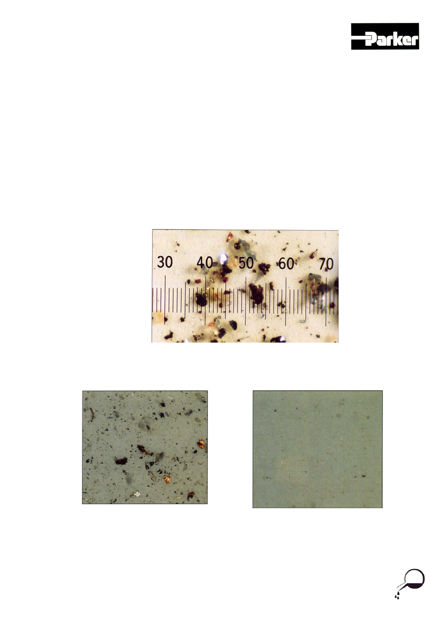
Figure 6.1 - Actual Photomicrograph of particle contamination Scale 1 division = 20
microns
Ref H F&C L1 0504
Fig 6.2 ISO 21/19/17 fluid (Magnification
100x)
Fig 6.3 ISO 16/14/11 fluid (Magnification
100x)
13
Level 1
Hydraulic Training
Hydraulic Fluids and Contamination
7.0 Other forms of contamination
So far we have looked at solid particles as a form of contamination. There are of
course other types of contamination that can cause damage to the pump and other
system components. Two of these (the most common) are discussed below.
7.1 Water
Water usually gets into a system because of condensation. Condensation forms on the
reservoir sides when the system is shut down, possibly over night as the system cools,
and is mixed in with the oil during start up the following morning. This form of
contamination is more common on mobile systems due to the changes in ambient
temperatures during night and day. One of the first signs of water contamination is that
the oil looks cloudy or milky. Condensation can lead to rust forming on the internal
surfaces of pumps and valves which in turn leads to solid particles breaking off and
contaminating the system.
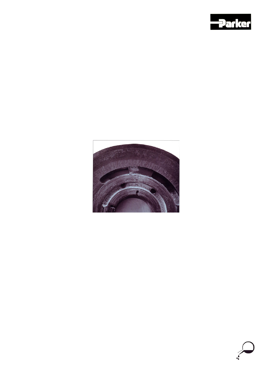
Figure 7.1 – Example of pump wear due to water contamination
7.2 Air
Air is not often thought of as a contaminant, but due to the nature of the oil / air mix it
can be detrimental to all hydraulic components, primarily the pump. Air can enter the
system through loose connections on the suction side of a cylinder or the suction side
of a pump. Air can cause cavitation in a system; cavitation can cause major component
damage in a hydraulic system and can destroy or seriously damage a pump in a matter
of minutes. A hydraulic system running with air in the system can sluggish and erratic
in operation. Air at the pump inlet will be very noisy due to cavitation taking place. The
system oil will show traces of minute air bubbles in the oil reservoir and in serious
cases foam will form on the oil surface in the reservoir.
Ref H F&C L1 0504
14

Level 1
Hydraulic Training
Hydraulic Fluids and Contamination
Ref H F&C L1 0504
15
Summary Points
There are three main groups of hydraulic oils
Mineral oils are the largest and most common group of oils
Mineral fire resistant oils are mixed with water
Man made synthetic oils are expensive compared to mineral oils
Environmentally friendly oils are becoming more prominent in the field
Viscosity measures of the resistance of oil to flow
Viscosity is measured in centistokes
The Pour point of an oil is the lowest temperature that the oil begins to
congeal
More than eighty percent of all hydraulic failures are as a direct result of
contamination
The smallest contaminant is generally the biggest cause of damage due to
the erosion of the small clearances between component parts
Reservoirs should be filled with oil which has passed through a sealed pre-
filling filtration system
Filters generally fall into three categories: suction, pressure and return